Tuesday 2 May 2017

RIPv2 Network Engineers Notes

RIPv2 General Characteristics.

  • Classless
  • Distance-Vector
  • Timer-based
Attribute Value
Transport Protocol UDP 520
Metric Hop Count, Max = 15 , 16 <- Infinite/Unreachable
Hello interval No Hellos are used.  Relies on regular full routing updates instead.
Update Destination 224.0.0.9 - Multicast for RIPv2
Update Interval 30 Sec


Example Topology


Steady State Route Exchange Info


  • Sends routing updates every 30 seconds by defaults - destined to the multicast address 224.0.0.9
  • Each update contains the full list of routes known to the router along with the metric.


Route Updates and Failure Handling
  • Any new route become known to the router will be sent out immediately with the updated metric. But in this case, the routing update will only include the new route information. These updates are called "Triggered" updates (Flash updates by Cisco). Example below - Adding a new 172.168.1.0/24 network to R1

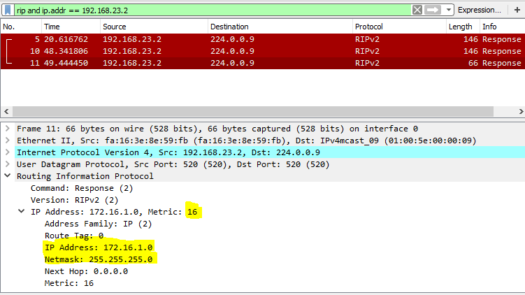
  • A route failure is propagated using the same mechanism. However, the way the receiving router would know the update is related to a "Failed" route and to tag that route as unreachable, is by looking at the metric.  The Metric of a failed/unreachable route is set to 16 so the receiver knows that route as an unreachable route and acts accordingly from that point onward. 
  • The metric 16 in RIP is regarded as the infinite metric. Hence, any route with the metric 16 is regarded unreachable. The mechanism of routes being tagged with metric of 16 to indicate the lack of reachability is known as "Route Poisoning"
  • In Route that becomes unreachable will removed from the routing tables as a valid route and be marked as a "Possibly Down" route. The route is kept in this state until the IFlushed after – Invalid after Seconds. See example below showing how the removal of the network 172.16.1.0/24 from R1 being notified to its neighbours. The capture below shows how the same information is carried further down via RIP updates (from R2 towards R3)


Routing Loop prevention

RIP uses several different methods to avoid routing loops. Described below;

  • Counting to Infinity:  If the next hop router to a particular prefix advertises the same route with a suddenly increased metric, It will accept the router and update its own metric. In case if the metric reaches infinity (16), that route will be discarded.
  • Split Horizon: A router will refrain from advertising a route back out an interface where the same interface is listed as the routes outgoing interface.
  • Split Horizon with Poisoned Reverse:  In this case, a router A will advertise a route learned via a particular interface out on that same interface, but with infinite metric (16). This is done to help the neighbouring router B to be aware of the fact that apart from the already known route by B, there is no alternative route via A

RIP Timers
  • Update Timer: The time that specifies the time interval over which the updates are sent. The default on Cisco device is 30 Seconds
  • Invalid after Timer: A per route timer. Gets reset everytime a new update is received for that specific route. If no updates are received for a specific route within the time defined by the  "Invalid after Timer", that specific route will be put into the "Invalid" state. And the "Holddown Timer" starts.  Defaults to 180 Seconds.
  • Holddown Timer: A per route timer that starts after a router has been tagged as Invalid. During the hold timer is in effect, the router will advertise the particular route as unreachable. The router will not accept any new modifications to this specific route from any neighbour even if the incoming update has a potentially valid route. Essentially, the route will be locked. down. Defaults to 180 Seconds
  • Flushed after Timer: A per route timer. Begins when an update about a specific route has been received from the next hop. After this timer expires, All information about the route will be completely flushed out from the RIP database.

Route filtering techniques

Controlling RIP advertisements on an interface: The "Network" command under the RIP process would only accept the classful form of network subnets (even if we enter a classless network, it will automatically reformat it to be a classful network). Therefore, it will enable RIP on all interfaces with subnetworks falling under that classful network which is not sometimes desirable. To overcome this issue, following techniques can be used to control each aspect.

  • Sending RIPv2 updates:  Can be disabled on individual interfaces by using "passive-interface Gig0/0" command under the RIP process.
  • Listening for RIPv2 updates: Filter all incoming routes using distribute list, or filter incoming RIPv2 packets using a per-interface ACL
  • Advertisement of Connection subnet: Filter outbound advertisements using distribute list filtering the corresponding connected subnet.
  • Advertising to specific neighbours on a Multi-access network:  Disable multicast updates using "passive-interface" command and use "neighbour 10.1.1.2" command under the RIP process.
  • Disabling auto-summarization at classful boundaries:  RIPv2 has "auto-summary" on by default. Therefore, subnetworks belonging to a specific classful network will only be advertised to a neighbour without modification as long as the neighbour is also connected by a subnetwork that falls under the same classful network. If not, it introduces a classful boundary. Hense, only a classful summary route will be advertised.  This can be stopped by "no auto-summary" command under the RIP process.


RIPv2 Authentication

  • Supports clear text and MD5 passwords.
  • Multiple keys can be used in conjunction with key-chain. 
  • Cisco supports authentication on a per-interface basis.
  • When authentication is enabled, the maximum number of routes that can be carried on the RIP update will be 24 instead of 25 as the Authentication data occupies the first slot. 
Example offset config below (adding 5 to the incoming metric for route 10.2.2.0/24 on Gi0/1 interface)


RIPv2 Offset Lists, Distribute List & Prefix Lists

  • Offset List: Used to manipulate the metric of a received or advertised route. 
    • Specific routes are selected based on ACL: Standard/Extended/Named
    • Can be applied IN or OUT under the RIP process
    • Can be applied to an Interface by referring to a particular Interface under the RIP Process
    • If no interface is referenced, all interfaces will be affected.
    • If a route doesn't match an entry on the offset list, those routes will not be affected.
  • Distribute List: Used filter inbound or outbound RIPv2 updates 
    • Can be applied to any interface
    • Applied under the RIP process
    • If an interface is not specified, the filtering will apply on all interfaces.
      • distribute-list { access-list-number | name } { in | out }[ interface-type interface-number ]
    • Distribute list can also be applied with a prefix-list
      • distribute-list prefix prefix-list-name { in | out } [ interface-type interface-number ]

    Wednesday 11 March 2015

    IEEE STP & PVSTP+ Interoperability - A Closer Look

    IEEE STP (802.1D) is the standard so it absolutely has no respect for anything other than IEEE BPDUs nor it will care about anything else. The only BPDU it understands is the IEEE BPDUs with the destination MAC address of 0180.C200.0000 without any tags (so no Dot1q TAG) encapsulated in IEEE 802.3 LLC Ethernet frames. That's it. End of story.

    So what  would happen if the following takes place:
    • If IEEE BPDUs arrive with a VLAN Tagg: THE BPDU will get dropped/will be ignored.
    • If IEEE BPDUs arrive with different Destination MAC address: Well, this doesn't make any sense, because STP enabled ports on the switch are not joined with any other Multi-cast group addresses other than IEEE STP: 0180.C200.0000 so the frame will be switched according to normal switching rules 
    • If something other than IEEE BPDU arrive: This is not even a question right? this is what switches do.. they simply switch frames out the port according to the MAC address table, if it doesn't know about the Destination MAC address yet, it will flood the frame out of all ports except for the port the frame came in. 
    • If it sees a Multi-cast Address other than something it is listening on? - Again normal switching rules apply, Switch will simply flood that traffic as well (let's say that IGMP, CGMP is not turned on) 
    • Wait.. What will happen if it sees a PVSTP+ BPDU. "Hmmm.. what? what PVSTP+ BPDU ? Haven't heard of anything like that before.." says IEEE STP (802.1D). To IEEE STP, this is simply an unknown Multicast frame. So the switch simply floods it out ports.

    It is vital to understand the above behavior or the "arrogance" of IEEE STP to understand why Cisco had to include all the bits and pieces and perform checks to make sure that the Cisco's flavor of STP, "PVSTP+" works in harmony with IEEE STP

    Now with this in mind. Lets think about what Cisco had to go through when they decided to come up with their own, more efficient STP/BPDU flavor while making sure that it can actually work with standard IEEE STP.

    First of all they can't just manipulate IEEE BPDU because it is the  standards and Cisco has to make sure that their switches support this standard as well.

    So they thought.. "hmmm what would allow us to develop our own BPDU protocol.." and someone at the back of the room said "I know! I know!.. why don't we use 802.3 SNAP Ethernet Format.. it allows us to define our own protocol specific to our Organization". And everyone was like.. "Dude you are Awesome!! :)".

    802.3 SNAP provides a way to identify your Organization and the custom protocol specific to that Organization. Basically once you've registered your Organization to have your own OUI which is a unique ID for the Organization, you can simply create your own protocols at Layer3 and above. If this doesn't make any sense to you.. please have a read on this article I wrote which explains ins and outs of modern Ethernet formats.

    Ok. So we are all set. We will be using 802.3 SNAP frames for PVSTP+ BPDUs.  So everyone is happy. All good. end of story...? Well, not so fast Cisco.., what if I want to connect my non-Cisco switches that runs IEEE STP with a Cisco switch that runs PVST+.

    Hmmm.. now you are talking.. Now Cisco has a problem to solve. 
    • PVSTP+ runs multiple Spanning Tree instances per VLAN. On the other hand, IEEE STP runs a single STP instance and that is not even attached to any VLAN. (No it doesn't have anything to do with VLAN1 - if that's what you were thinking). So Cisco has to pick an STP instance that is mapped to some vlan. This STP instance will then be made responsible to inter-operate with IEEE STP. 
      • So Cisco Picked the STP instance attached to VLAN1. Which means that, on Trunk (dot1q) links, regardless of the Native VLAN, The Cisco switch (that runs PVSTP+) will use its VLAN1 STP instance to communicate with switches that only understand IEEE STP. 
    • Now, as we discussed earlier, the IEEE STP only understands and care about IEEE BPDUs, so if you want your PVSTP+ VLAN1 instance to communicate with IEEE STP switches, the only way to do this is by making sure that when PVSTP+ deals with IEEE STP, it uses the only language that IEEE STP understands, "Untagged IEEE BPDUs". Meaning, you will have to convert the VLAN1 PVSTP+ BPDUs in to (untagged) IEEE STP BPDUs on these links.
    • So what about the Access ports that plug in to IEEE STP switches.... 
      • Cisco switches always use IEEE BPDUs on its Access ports by default. So problem solved. 
      • If you have a IEEE STP switch connected to the Cisco switch that runs PVSTP+ plugged in on "access VLAN 10" port, Cisco switch will send out untagged IEEE BPDUs out that port. Which essentially means that the VLAN 10's STP instance on Cisco switch will converge with IEEE STP instance on the non-Cisco switch.
    In summary, we can narrow this behaviour down to following,
    • On trunk ports Cisco sends out IEEE BPDUs (untagged of course) corresponding to its VLAN1's PVSTP+ STP instance REGARDLESS of the Native VLAN configured on the trunk.
    • On Access Ports, Cisco switches will always send out IEEE BPDUs (untagged) corresponding to that VLAN configured on that Port
    • Is that all?.. well not really. There are other cases  that Cisco had to sort out. Specifically the following.
      • What happens if the Cisco port is connected to a shared Medium and within that shared Medium we have mixed Cisco and Non-Cisco switches  and you want All Cisco switches within that shared segment to run PVSTP+ and Cisco and non-Cisco switches to Inter-operate at the same time.
        • Well, we already discussed how the Cisco & Non-Cisco switches will sort things out. Cisco switch simply sends out untagged IEEE BPDUs correspond to VLAN1. So no problems there..  
        • The issues is that, if the segment is also shared with Other Cisco switches that runs PVSTP+, those switches need to receive PVSTP+ BPDUs pertaining to each VLAN instance so they can converge per VLAN instance. So the solution is, you simply send out PVSTP+ BPDUs out that port Tagged with relevant VLAN ID. 
        • What about the Native VLAN.. are we Tagging PVSTP+ BPDUs with Native VLAN ID as well?.  NO. PVSTP+ BPDUs pertaining to the Native VLAN on that port will be sent out without the DOT1Q tag.
      • How about VLAN1, we are already sending out IEEE BPDUs out the port.. does this mean that the port also sends out PVSTP+ BPDUS in addition to that ? 
        • YES it would send out PVSTP+ BPDUs pertaining to VLAN1 instance as well, Tagged or unTagged depending on the Trunk's Native VLAN configuration.

    Let's consider following scenarios,

    Let's consider different port configurations and see what types of STP frames we can expect in each case.

               Access Port BPDU Generation:

                   Access VLAN 100 : 
      • UNTAGGED : IEEE BPDUs corresponding to VLAN 100 
                   Access VLAN 200 :
      • UNTAGGED : IEEE BPDUs corresponding to VLAN 200
                   Access VLAN 1     :
      •  UNTAGGED : IEEE BPDUs corresponding to VLAN 1

    Trunk port BPDU Generation, 

          Native VLAN 1, Allowed VLAN 1,100,200 : 
    • UNTAGGED              : IEEE BPDUs Corresponding to VLAN 1
    • UNTAGGED              : PVSTP+ BPDU Corresponding to VLAN 1
    • TAGGED VLAN 100 : PVSTP+ BPDU Corresponding VLAN 100
    • TAGGED VLAN 200 : PVSTP+ BPDU Corresponding VLAN 200
          Native VLAN 100, Allowed VLAN 1,100,200 : 
    • UNTAGGED               : IEEE BPDUs     Corresponding to VLAN 1
    • TAGGED VLAN 1      : PVSTP+ BPDU Corresponding to VLAN 1
    • UNTAGGED               : PVSTP+ BPDU Corresponding to VLAN 100 
    • TAGGED VLAN 200  : PVSTP+ BPDU Corresponding to VLAN 200
         Native VLAN 200, Allowed VLAN 1,100,200 :
    • UNTAGGED              : IEEE BPDUs corresponding to VLAN 1
    • TAGGED VLAN 1     : PVSTP+ BPDU corresponding VLAN 1
    • TAGGED VLAN 100 : PVSTP+ BPDU corresponding VLAN 100
    • UNTAGGED              : PVSTP+ BPDU corresponding VLAN 200

    More cases that Cisco had to deal with.

    Cisco hates Native VLAN miss-matches for obvious reasons. But as you can see, this whole BPDU UNTAGG'ing business is a recipe for a native VLAN mismatch. For example, what would happen if you have two switches (Switch-1 and Switch-2) connected with a trunk. Switch-1 has native VLAN 100 configured on its trunk port whereas Switch-2 has native VLAN 200. 

    In this case, from the Switch-2's perspective, it receives UNTAGGED PVSTP+ BPDUs which will be put in to VLAN 200 and process within VLAN 200 STP instance. This is what the Native VLAN configuration do to untagged frames. But if you think about it, these UNTAGGED PVSTP+ BPDUs were sent by the Switch-1, and it was only untagging VLAN 100 BPDUs. So we officially created a Native VLAN mismatch.

    So Cisco was wondering.. can we somehow indicate the Original VLAN information inside the UNTAGGED PVSTP+ BPDUs ?. And a Cisco employee who was sitting in the corner of the Room said "Hey why don't we just introduce a new TLV record in to the PVSTP+ BPDU and simply indicate this info in there.. " and everyone was like.. Dude can we do that ?. And the Cisco employee is like "Well this is our protocol.. we can do anything with it right..?" and Everyone was like... "man you are a genius !!"

    So Cisco decided to introduce a special TLV record to indicate the original VLAN information inside the PVSTP+ BPDUs for all VLAN instances including the Native VLAN.

    For example,

    Trunk port, Native VLAN 1, Allowed VLAN 1,100,200 : 
    • UNTAGGED : IEEE BPDUs corresponding to VLAN 1
    • UNTAGGED  : PVSTP+ BPDU corresponding to VLAN 1 , TLV -> Original VLAN 1
    • TAGGED VLAN 100 : PVSTP+ BPDU corresponding to VLAN 100 , TLV -> Original VLAN 100
    • TAGGED VLAN 200 : PVSTP+ BPDU corresponding to VLAN 200 , TLV -> Original VLAN 200
    Trunk port, Native VLAN 100, Allowed VLAN 1,100,200 : 
    • UNTAGGED : IEEE BPDUs corresponding to VLAN 1 - 
    • TAGGED VLAN 1 : PVSTP+ BPDU corresponding to VLAN 1 , TLV -> Original VLAN 1
    • UNTAGGED : PVSTP+ BPDU corresponding to VLAN 100 , TLV -> Original VLAN 100
    • TAGGED VLAN 200 : PVSTP+ BPDU corresponding to VLAN 200 , TLV -> Original VLAN 200

    Well that resolves the problem right. Now the receiving switch can check whether the Native VLAN configured on its port actually matches the TLV indicated VLAN. So the switch knows exactly that is it not mixing VLANs. If a Switch finds out discrepancies, it will go in to Port Inconsistent state and error-disable the port. (by the way.. CDP can also detect VLAN mismatches using its own mechanism)

    Before moving forward, we need to clarify one thing.. As you can see, Between the two Cisco switches, Both types of BPDUs are exchanged for VLAN1. So which one gets the priority? Always IEEE BPDUs. PVSTP+ BPDUs are there to help switches to identify any misconfiguration in the transit path using its TLV field.

    More Cases To Understand

    What happens if the Two Cisco switches are connected through a non-Cisco switch and both inter-switch links are configure as trunks. 
    As for the Non-Cisco Switch, everything is sorted. It only understands IEEE BPDUs and both Cisco switches connected to it send out IEEE BPDUs (corresponding to their VLAN1 instance) and the Non-Cisco switch sends out IEEE BPDUs (NOT attached to any VLAN by the way) towards the Cisco switches where they get processed as a part of VLAN1's PVSTP+ instances in each Cisco switches. Actually, this behavior wouldn't really depend on changes made on any of the THREE switches or switch ports. So we are all good as far as the Non-Cisco switch goes..

    How about the Cisco Switches? Well let's see how it would behave in different scenarios. 
    • Switch-1 Trunk port configuration: Native VLAN 1, Active VLAN 1,100,200 , Allowed VLANs on the Trunk: ALL 
    • Switch-2 Trunk port configuration: Native VLAN 1, Active VLAN 1,100,200 , Allowed VLANs on the Trunk: ALL 
    What Switch-1 Sends outWhat Switch-2 Receives
    UNTAGGED : IEEE BPDUs corresponding to VLAN 1UNTAGGED : IEEE BPDUs (Originated byNon-Cisco Switch) - Processed against the VLAN1 PVSTP+ instance
    UNTAGGED : PVSTP+ BPDU corresponding VLAN 1, TLV -> Original VLAN 1UNTAGGED : PVSTP+ BPDU, TLV -> Original VLAN 1 (Not being processed further. Informational Only)
    TAGGED VLAN 100 : PVSTP+ BPDU corresponding VLAN 100, TLV -> Original VLAN 100TAGGED VLAN 100 : PVSTP+ BPDU, TLV -> Original VLAN 100 - Processed against the VLAN100 PVSTP+ instance
    TAGGED VLAN 200 : PVSTP+ BPDU corresponding VLAN 200, TLV -> Original VLAN 200TAGGED VLAN 200 : PVSTP+ BPDU, TLV -> Original VLAN 200 - Processed against the VLAN200 PVSTP+ instance


    As you can see, we don't have any issues here. Everything is working as normal. No VLAN missmatch. Life is beautiful.. :)

    OK Let's say, on the Non-Cisco Switch, port connecting to the Switch-1 has been configured so it Tags the untagged traffic as VLAN 200 (equivalent to Native VLAN 200 command). Let's see how this is processed by @ Cisco switch-2

    What Switch-1 Sends outWhat Switch-2 Receives
    UNTAGGED : IEEE BPDUs corresponding to VLAN 1UNTAGGED : IEEE BPDUs (Originated byNon-Cisco Switch) - Processed against the VLAN1 PVSTP+ instance
    UNTAGGED : PVSTP+ BPDU corresponding VLAN 1, TLV -> Original VLAN 1TAGGED VLAN 200: PVSTP+ BPDU, TLV -> Original VLAN 1 - (200 != 1) VLAN Inconsistent port.
    TAGGED VLAN 100 : PVSTP+ BPDU corresponding VLAN 100, TLV -> Original VLAN 100TAGGED VLAN 100 : PVSTP+ BPDU, TLV -> Original VLAN 100 - Processed against the VLAN100 PVSTP+ instance
    TAGGED VLAN 200 : PVSTP+ BPDU corresponding VLAN 200, TLV -> Original VLAN 200TAGGED VLAN 200 : PVSTP+ BPDU, TLV -> Original VLAN 200 - Processed against the VLAN200 PVSTP+ instance


    As you can see here, the non-Cisco switch will simply Tagg the PVSTP+ BPDUs as VLAN 200 (To the non-Cisco switch, this is just random Multicast traffic) and it will send this traffic out as VLAN 200 TAGGED traffic towards Cisco Switch-2. Before processing the BPDU within VLAN 200 STP instance, Cisco Switch-2 will check if the VLAN TAG (200) matches the VLAN indicated in the TLV field (1). In this case it doesn't, so it will put that port in to vlan inconsistent state.

    Ok, Next we reconfigure Switch-2 so it will have Native VLAN as 100 and remove Non-Cisco switch's Un-tagg 200 configuration.,

    • Switch-1 Trunk port configuration: Native VLAN 1, Active VLAN 1,100,200 , Allowed VLANs on the Trunk: ALL 
    • Switch-2 Trunk port configuration: Native VLAN 100, Active VLAN 1,100,200 , Allowed VLANs on the Trunk: ALL
    What Switch-1 Sends outWhat Switch-2 Receives
    UNTAGGED : IEEE BPDUs corresponding to VLAN 1UNTAGGED : IEEE BPDUs (Originated byNon-Cisco Switch) - Processed against the VLAN1 PVSTP+ instance
    UNTAGGED : PVSTP+ BPDU corresponding VLAN 1, TLV -> Original VLAN 1UNTAGGED : PVSTP+ BPDU, TLV -> Original VLAN 1 - Tagged with VLAN 200 as it enters the Port: Native VLAN Miss match
    TAGGED VLAN 100 : PVSTP+ BPDU corresponding VLAN 100, TLV -> Original VLAN 100TAGGED VLAN 100 : PVSTP+ BPDU, TLV -> Original VLAN 100 - Processed against the VLAN100 PVSTP+ instance
    TAGGED VLAN 200 : PVSTP+ BPDU corresponding VLAN 200, TLV -> Original VLAN 200TAGGED VLAN 200 : PVSTP+ BPDU, TLV -> Original VLAN 200 - Processed against the VLAN200 PVSTP+ instance

    As you can see, on Switch-2, Since the Native VLAN is configured as 200, any untagged frame coming in to the Switch will be tagged as VLAN 200 before it being processed (except for the IEEE BPDUs, IEEE BPDUs always gets processed against VLAN 1 regardless of the native vlan configuration on the port as discussed earlier). But in this case, if the switch processed the incoming Untagged PVSTP+ BPDU against the VLAN 200 STP instance, that would be wrong since the BDPU was actually originated on VLAN1 on Switch-1. So with the help of of TLV field, the switch can now determine if there's a discrepancy with the VLAN configuration and if any found, the port will go in to Native-VLAN mismatch "Inconsistent Peer VLAN ID" state.

    Let's take another scenario, This time, the Native VLAN is changed on the Switch-1 to be VLAN 200 (nothing fancy done on the non-Cisco switch) 

    • Switch-1 Trunk port configuration: Native VLAN 200, Active VLAN 1,100,200 , Allowed VLANs on the Trunk: ALL 
    • Switch-2 Trunk port configuration: Native VLAN 1, Active VLAN 1,100,200 , Allowed VLANs on the Trunk: ALL

    What Switch-1 Sends outWhat Switch-2 Receives
    UNTAGGED : IEEE BPDUs corresponding to VLAN 1UNTAGGED : IEEE BPDUs (Originated byNon-Cisco Switch) - Processed against the VLAN1 PVSTP+ instance
    TAGGED VLAN 1 : PVSTP+ BPDU corresponding VLAN 1, TLV -> Original VLAN 1TAGGED VLAN 1: PVSTP+ BPDU, TLV -> Original VLAN 1 (Not being Processed further - Informational Only)
    TAGGED VLAN 100 : PVSTP+ BPDU corresponding VLAN 100, TLV -> Original VLAN 100TAGGED VLAN 100 : PVSTP+ BPDU, TLV -> Original VLAN 100 - Processed against the VLAN100 PVSTP+ instance
    UNTAGGED : PVSTP+ BPDU corresponding VLAN 200, TLV -> Original VLAN 200UNTAGGED : PVSTP+ BPDU, TLV -> Original VLAN 200 - Tagged with VLAN 1 as it enters the Port: Native VLAN Miss match


    In this case, Switch-2 will receive Untagged PVSTP+ BPDUs that would be put in to VLAN1. But with the help of TLV field, it can figure out that the BPDU has originated from VLAN 200. So the switch knows that there is a Native VLAN Missmatch in the transit path.

    Ok one last scenario, this one is a bit fancy.. Consider 2 Cisco switches configured as follows.

    Cisco Switch-1 <--> Non-Cisco Switch-1(Native VLAN 100) <-->(Native VLAN 200) Non-Cisco Switch-2 <--> Cisco Switch-2 
    As you can see, what we are doing here is, basically swapping the VLAN 100 with 200 as it traverses the non-Cisco switches. The "Native VLAN 100" means that, it will Untag VLAN 100 as the frame gets sent out on that port and will Tagg the untagged frames arriving at the port with VLAN 100 before it enters the switch. We also have the Cisco switches configured with proper native VLAN assignments (no discrepancies in the configuration) 

    • Switch-1 Trunk port configuration: Native VLAN 1, Active VLAN 1,100,200 , Allowed VLANs on the Trunk: ALL 
    • Switch-2 Trunk port configuration: Native VLAN 1, Active VLAN 1,100,200 , Allowed VLANs on the Trunk: ALL 
    Ok let's analyze behavior here..

    What Switch-1 Sends outWhat Switch-2 Receives
    UNTAGGED : IEEE BPDUs corresponding to VLAN 1UNTAGGED : IEEE BPDUs (Originated byNon-Cisco Switch) - Processed against the VLAN1 PVSTP+ instance
    UNTAGGED : PVSTP+ BPDU corresponding VLAN 1, TLV -> Original VLAN 1UNTAGGED : PVSTP+ BPDU, TLV -> Original VLAN 1 (Not being processed further. Informational Only)
    TAGGED VLAN 100 : PVSTP+ BPDU corresponding VLAN 100, TLV -> Original VLAN 100TAGGED VLAN 200: PVSTP+ BPDU, TLV -> Original VLAN 100 - TAGG(200) doesn't Match the TLV field ,VLAN(100) - VLAN Inconsistent port
    TAGGED VLAN 200 : PVSTP+ BPDU corresponding VLAN 200, TLV -> Original VLAN 200TAGGED VLAN 200 : PVSTP+ BPDU, TLV -> Original VLAN 200 - Processed against the VLAN200 PVSTP+ instance

    As you can see, the non-Cisco switches will now effectively swap the VLAN ID between 100 <->200. But they CAN'T and WON'T change the TLV field (because switches, by definition don't change stuff inside the Payload/BPDU). So whatever the changes made at the transit can be detected by comparing the incoming Tagg with the TLV. So in this case, Cisco Switch-2 will put the port in to VLAN inconsistent state and error disable it.

    IEEE STP & PVSTP+ Convergence

    Now that we understand how the BPDU works at a much deeper level, Let's have a look at the big picture and see how all these things work together to build a loop free topology in each area (Cisco & Non-Cisco) of the switching infrastructure. 

    Let's consider the following Switching arrangement where you have 4 Non-Cisco switches connected to two sets of Cisco switches as shown below.


    So I guess, we covered most cases if not all. It's easier to understand why the protocols are implemented the way they are than memorizing random facts about it. So you can derive the result of any scenario that you come across.

    If you find any missing facts or any other interesting scenarios, please note them in the comment section.. that would be beneficial for everyone :)


    Tuesday 10 February 2015

    Things You Should Know About VTP Versions

    Cisco has introduced several versions of VTP protocols over the years trying to overcome the issues pertaining to the earlier version of the same.  The latest version available today is version 3. As a Network Engineer you should know exactly the differences between each version and most importantly, the security impact  it can have on your network so you can make an educated decision whether to use this tool or not.

    So before going to deep, What is it?

    Well in a nutshell, it is a protocol that should make your life easier by propagating VLAN information  throughout your switching infrastructure. 

    First of all, let's take a look at each protocol and go over their features.

    VTP Version and Feature differences


    VTP version 1
    • Only supports the "normal" range VLANs (1 - 1005) 
    • Default VTP version on Enterprise IOS based switches 
    • Plain Text password or MD5 password 
    • Modes operated in :  Server/Client or Transparent modes
    VTP version 2
    • Supports the normal range VLANs (1 - 1005) 
    • If Extended VLAN (1006 -4094) support is needed, then the switch needs to be put in the Transparent mode. 
    • Adds unknown TLV support 
    • Supports Token Ring Concentrator Relay Function and Bridge Relay Function 
    • Optimized VLAN database consistency checks 
    • Plain Text password or MD5 password
    • Modes operated in :  Server/Client or Transparent modes
    VTP version 3 

    • Supports Extended VLANs.
    • Private VLAN support 
    • VTP "off" mode support (also supported per interface basis)
    • SPAN VLAN support
    • Password Storage and usage has been improved 
    • Option to store the password in encrypted format (so you can't read the real password from the configuration file). The encrypted string can be applied (copy pasted) to other switches directly. This password should be entered in plain text when you promote the server to the PRIMARY server (find more info on primary servers below). 
    • To improve security (specially to remedy some of the major issues with VTP v1/v2), following server roles are defined.
      • Primary Server 
      • Secondary server 
        • The Primary server state is a run-time state and kept in the running-config only. Only the Primary server is allowed to modify VTP Domain content. Secondary server CAN NOT change anything unless you promote it to be the Primary server in which case the existing primary server will go back to being a Secondary server. The server role is changed at the privilege exec level.

    VTP Transparent mode (All Versions) - things you might want know:

    • If the configured domain is NULL (which is what you get if you didn't configure anything), All VTP versions will pass VTP messages without checking the domain name of the incoming VTP message.
    • If the Domain is configured, then only the matching VTP messages will be forwarded everything else will be dropped.

    VTP version 1 & 2 message Structure


       Message Types:
    1. Summary Advertisement 
    2. Subset Advertisement 
    3. Advertisement Request 
    4. Join Messages

       Summary Advertisement:

    • Sent by the Server and Client every 5 Mins and at each modification to the VLAN Database
    • This carries the info about: Domain Name, Revision Number, ID of the last update, Timestamp, Last update timestamp, MD5 hash calculated over the content of VLAN database and the VTP Password (- if configured ) and the number of Subset Advertisement messages that optionally follow this Summary Advertisement. Summary Advertisements DO NOT carry any VLAN Database contents. 
       Subset Advertisement:
    • Sent by Servers and Clients after a modification is made on the VLAN database
    • Carries full content of the VLAN Database
    • If the VLAN DB is too big, there may be more than one Subset Ads being sent

       Advertisement Request:

    • Originated by both the VTP Server and the clients when reloaded, When a switch goes in to the client mode or  when a Summary Advertisement is received with a higher configuration revision number.

       Join Message:
    • Sent by Every server and client every 6 seconds IF VTP pruning is active. This message includes information as to which VLANs are actually being used or not (=pruned)


       VTP v1/v2 important notes:

    • Both the Client and Server can send VTP updates. So even the client can update a server as long as the VTP revision number is higher and the Password/domain name is the same.
    • The VTP Summary Advertisement carries a MD5 hash calculated on the Database content and the Password.
    • The MD5 password DOES NOT provide any protection to the data.. it is only used to indicate changes taken place in the vlan database or the password itself.

    VTP v3 improved Security and Features

    • Only the primary server's VTP updates are allowed to propagate within the network.
    • Switch will only update its database if the incoming VTP agrees with the domain, the primary server and VTP password.
    •  You can only make VLAN changes to the primary server. 
    •  You can't make changes to the vlans while the switch is either in Client mode or a secondary server mode (not the Primary Server). If you try to add VLANs on a client switch or a secondary server, it will throw an error
    •  When a switch is made a primary server (using "vtp primary" command), it will flood it's vlan database and all clients will install and flood it further down EVEN IF THE primary servers revision number is lower.
    • With version 3, it is no longer possible to reset the revision number by putting the switch in to transparent mode and back. This can only be achieved by changing the VTP password or changing the domain name.
    • With VTP v3, Since it also supports distribution of other "kinds" of information such as MST information, you can change the role of the VTP server per feature separately. For an example, within the same switch, you can make the switch primary for the "feature" VLAN and secondary of the feature MST.

    VLAN-DB Storage and Configuration Chart.


    ItemVersion 1Version 2Version 3
    normal VLAN range supported? (1 - 1005)YesYesYes
    normal VLAN range configuration kept in..vlan.dat : in normal modes
    running-confi : in Transparent mode
    vlan.dat : in Normal modes
    running-confi : in Transparent mode
    vlan.dat : in Normal modes
    running-config : in Transparent/Off mode
    Normal Range can be configured invlan-db mode or
    Gloabal configuration mode
    vlan-db mode or
    Gloabal configuration mode
    Global configuration mode (There is no vlan-db mode)
    Extended vlan support ? (1006 - 4094)NOOnly in Transparent modeYes - in All modes
    Extended Range  VLAN configuration kept inN/Arunning-config : In Transparent mode onlyvlan.dat: in Normal modes
    running-config: in Transparent/Off mode
    Extended Range can be configured in-vlan-db mode or
    Global configuration mode
    Global configuration mode
    (There is no vlan-db mode)


    Security Analysis and Best Practice

    VTP version 1 & 2

    The most talked about security issue when considering VTP is the complete deletion or rewrite of the VLAN database. This is quite possible especially with version 1 & 2 due to the fact that the protocol allows any switch ( regardless of whether it is a Client or a Server) to flood seemingly a "newest" copy of the vlan database resulting in all of the other switches  rewriting  their vlan database.
    Now.. this is not that simple, In order for the switches to accept a new copy of vlan database via VTP protocol (version 1 & 2) it should pass following conditions (- So yeah.. we do have some security measures :)
    1. Domain name should be the same
    2. VTP configuration revision number should be higher than what is currently stored in the vlan db
    3. The password should be the same - If configured
    So if you think about the scenarios that this can happen, 
    the most likely cases are, you plugging in your own LAB switch in to the network (which already configured with password and Domain name) and sadly wipe out everything. Of course this is recoverable if you backed up your vlan.dat file - which is where the VTP information is stored.

    Another case would be that a bad person gains access to your network, plugs in his/her switch and wipes the VLAN information  within the network. Now in this case, if you haven't configured a password, the attacker can simply plug in a switch and even learn the Domain name by simply not configuring a domain name in his/her switch initially. So make sure you configure a password if you are running VTP version 1/2. Also never leave your switch ports at default allowing them to perform trunking with attacker's switch ( VTP only passes through Trunks and NOT through Access Ports).

    Also the fact that there can be more than one VTP server in the network,  can make things a little bit confusing when administering the network. But of course if you (and your colleagues) are well disciplined to always use a single server switch ,  This shouldn't be an issue.

    Furthermore, These versions don't support extended VLANs. So you are stuck with the normal VLAN range which may not be a big issue.. but personally I like the freedom of using all available numbers in a sensible manner.

    VTP version 3

    Compared to it's predecessors, This is the best version yet from both feature and security stand points.
    The "complete VLAN loss" problem we talked about earlier is highly unlikely here with the  introduction of the Primary and Secondary server concept.

    Well, let's talk about this briefly..

    So the idea is, you can still have multiple servers but at any given time, You would only have a SINGLE primary server and there can be as many Secondary servers or none. But wait.. what if we configure all of them to be primary servers ??
    well.. you can't. Being the "Primary Server" is only a run-time state and is not pre-configurable in the start-up config or any other place. All the switches in the domain will agree on who is the Primary server at a given time and accept and flood VTP information  that belong to this Primary Server only.  If you go to a secondary server and make it a primary server, the previous Primary will become a secondary AUTOMATICALLY. So no conflicts. Does this mean that you can simply change any Secondary server to a Primary? Not really, you need to enter the VTP password first (which is not readable off the config file like in v1/v2). So there is some security layer.

    What would happen If you take the existing  switch off of the network, then put it in to the Primary Server mode (if not already the primary), and change some vlans and add it back to the network?, 
    Even though this switch has a higher revision number and it has been a Primary Server previously with the correct password, All other member switches will NOT agree on it's validity of being a Primary server anymore (Since they already have a legit primary server registered at the time). So the neighbor switches will not accept any updates from this switch.

    Another thing to remember when deciding to use (or migrate to) VTP version  3 is that, it does not work with VTP version1-only switches. If the VTP v3 switch detects switch that supports v1 and v2 it will force the switch to work on VTP version2 (thanks to Martin @ IEOC for pointing out this missing infomation)

    Summary

    • If you have the option, definitely go with Version 3. It's much more secure and feature-rich.
    • There is no reason to use VTP version 1 since almost all the switches today support version 2 so use that
    • If you are using VTP version 2, make sure you have a password configured and port security is maintained
    • If you are suing VTP version 2, Definitely keep an updated vlan.dat backup somewhere safe
    • Be mindful when swapping out switches.

    VTP is not a bad thing if you are using it right, It will make your life so much easier when dealing with large number of switches.

    Let me know what you guys think..  Have I missed any points here. Please leave a comment below.

    Thursday 29 January 2015

    Ethernet Standards

    Going through my CCIE studies, I wanted go deeper into the Ethernet standards and their usage. I've put together following notes on the most important facts surrounding these topics. Hope you'd find this helpful :)

    What are we trying to do with Ethernet?


    So the whole goal of a Layer 2 protocol should be to provide some means of identifying the start of the incoming frame (could also be considered as Layer 1 function) while providing some form of an indication as to what type of payload (Layer3 process) it carries through and some defined criteria to identify and accommodate the communication between endpoints with in a segment.

    In order to facilitate these requirements, over the years, following Ethernet types/standards have been defined.
    1. Ethernet II                  (also called DIX)
    2. IEEE 802.3                 (also referred to as IEEE 802.3 LLC)
    3. IEEE 802.3 SNAP
    4. Ethernet - Raw
    Let's take a look at each Ethernet standard and discuss the importance of each standard.

    Ethernet II (DIX)

    Ethernet II came first and this frame format was introduced by the three vendors, Digital Equipment Corp., Intel, and Xerox (hence the name "DIX") as a result of a joint research carried out in the beginning. This is the simplest form of all Ethernet standards and the most commonly used one today- probably due to its simplicity and  because it was there from the beginning.

    Now let's take a closer look at how the frame is structured.


    It uses its first 8 bytes (Preamble) to indicate the start of frame by arranging the first 62 bits as alternating "1/0s" and the last two bits as "1"s. Like so, 010101010101010...........................10101011
    So when the receiving end sees the "11" it knows where the actual Ethernet header starts. The alternating 1s and 0s will also allow the two endpoints to sync their internal clocks. According to my research, the two end points generally sync up within the first 14 bit time window.
    The Preamble function is the same for all Ethernet standards. So I'm not going to elaborate on this again for other Ethernet standards.

    The next two octets are used to indicate the Destination and the Source MAC addresses and this is also the same for all Ethernet standards.

    The "Type/Length" field is used to indicate the "Type"of the payload (= Layer 3 protocol) which is indicated as a Hexadecimal value. Now.. in the case of Ethernet II, this field is used only to indicate the Type whereas with other Ethernet standards (discussed later), This field is used to indicate the Length. We will later discuss how this field is used in a way so the Ethernet controller won't get confused trying to figure out if the value refers to a Type or a Length.

    Let's look at some EtherType examples,

    Some common EtherTypes:
    • IPv4      : 0x0800
    • ARP      : 0x0806
    • IPv6      : 0x86DD
    • LLDP    : 0x88CC
    • FCOE   : 0x8906
    • 802.1Q : 0x8100
    Note that all EtherTypes defined are always higher than the value 0x0600.  This is not a coincidence, this is done on purpose, Why?  keep on reading and you'll know..

    Packet capture of an Ethernet II frame:

    Below is a packet capture showing a real life example. This is for IPv4. Note the EtherType 0x0800


    IEEE 802.3


    IEEE 802.3 is basically the standardized, extended version to the Ethernet II.
    So what was done here is, without defining the EtherType (or Layer3 Protocol ID) as a part of the MAC/physical layer, the functionality has been moved to a new upper sub layer protocol as defined in LLC (802.2). This is more of an effort to make the frame format comply with the 7 Layer OSI model (in which case the MAC/Ethernet fields are considered as part of Layer-1 and Layer-1 upper sub-layers)

    LLC  introduces a new way of defining the EtherType (Layer 3 Payload type) and also enables some additional capabilities like error correction and flow control at layer 2.

    Lets first look at the Frame format first.


    Expanded LLC/802.2 Format


    As you can see, the previously used EtherType field is now solely used to indicate the "Length" of the Payload. Now.. if you think about it, we have a fundamental problem here...  an Ethernet controller that supports both Ethernet II and IEEE 802.3 has to have some mechanism to  distinguish between the two frame types (Ethernet II vs IEEE 802.3) just by inspecting the Length/Type field. But how ?

    Well, easy...  You make sure you assign all Layer 3 protocols with an EtherType number higher than 0x0600 which corresponds to the decimal value of 1536 which is greater than the maximum byte size of an Ethernet encapsulated payload. So with this rule, if the Type/Length field evaluates to a value less or equal to 1500, you can assure that it corresponds to a "Length" and thereby deciding that this is an IEEE 802.3 frame. If it is higher than 1500, it should be referring to an EtherType assignment so it's  an Ethernet II frame (- and this is why all your EtherTypes have Hex values higher than 0x0600, So now you know...)

    LLC introduces two fields, SSAP and DSAP basically referring to the Layer 3 protocol Types of the Source and Destination. In a more general case, for a given communication, the SSAP and DSAP addresses should contain the same value.. right? For example, if this is an IP communication, the source and the destination both will use IP as the Layer 3 protocol. The registered SAP address for IP protocol is 0x06, so in this case the numbers would be, SSAP = 0x06 and DSAP = 0x06.

    It should be noted that in LLC, with the concept of  SAP (Service Access Point), if you ever implemented two different Layer-3 protocols with different SAP IDs and architectured them in a such way so they can understand and interact with each other, LLC will facilitate the pathway for these two protocols to communicate - But there are very few protocols that behave this way. (I actually found pair of these during my research but totally forgot where it was.. :) I believe it's something to do with Token Ring - Maybe someone can point this out in the comment section

    Some registered SAP assignments:
    • 0x00   Null LSAP
    • 0x06   ARPANET Internet Protocol (IP)
    • 0x18   Texas Instruments
    • 0x42   IEEE 802.1 Bridge Spanning Tree Protocol
    • 0x7E   ISO 8208 (X.25 over IEEE 802.2 Type 2 LLC)
    • 0x80   Xerox Network Systems (XNS)
    • 0x98   ARPANET Address Resolution Protocol (ARP)
    • 0xAA SubNetwork Access Protocol (SNAP)
    • 0xF0   IBM NetBIOS
    • 0xE0   IPX
    • 0xFF   Global LSAP
    • 0x43   STP (802.1D)/RSTP/MST
    The Control field in LLC provides segment-to-segment flow and error control capabilities at Layer 2 which is something almost never used in today's IP based communications as the same functionality is provided at Layer 4 by TCP or some Application specific mechanism. The only difference is that TCP does this as an end-to-end protocol sitting between the source and destination as opposed to the segment-to-segment controlling facilitated here with LLC.

    LLC defines 2 flow types, 
    1. Type1 - Connection-less unreliable 
    2. Type2 - Connection oriented reliable

    When LLC operates in Type1, this is called an Unnumbered Information (UI) Frame and the control field value is set to  0x03. You will see this value set in LLC header in almost all modern communications. (Check the packet captures provided below showing the control field value)

    Note that, LLC is a standard on it's own and is not something specifically defined for Ethernet. It is intended to be used in conjunction with any OSI complaint communication system. So there's much more to this than what is explained here. If you need more information find some good information here:
    http://standards.ieee.org/getieee802/download/802.2-1998.pdf
    https://www.princeton.edu/~achaney/tmve/wiki100k/docs/IEEE_802.2.html

    Note that the diagram above depicts an 8 Byte preamble, The IEEE 802.3 standard regards to this as 7 byte preamble + 1 byte SFD (Start of Frame Delimiter) to better represent its functioning. But technically nothing's changed. So nothing's new there. This is true for the IEEE 802.3 SNAP standard which we take a look at next.

    Packet capture of an IEEE 802.3 frame:

    Below is a packet capture showing a real life example. This is a BPDU frame of 802.1D. Note the DSAP,SSAP  and the Length field assignments.


    IEEE 802.3 SNAP

    After the initial IEEE 802.3 release, IEEE soon realized that the 1 byte allocated for SAP assignment is not enough to accommodate future needs. So they basically came up with a clever 'hack' on the original IEEE 802.3 standard to facilitate more Layer 3 Payload types.

    They introduced another header (or a protocol if you will) called SNAP (Sub-Network Access Protocol) and inserted it immediately after the LLC (802.2) header and assigned a new LLC/SAP address 0xAA for this  new protocol. Let's have a closer look at the frame format and discuss the important aspects of it.


    SNAP header is 5 Bytes long, 3 Bytes allocated for OUI (Organizational Unit Identifier/ Vendor ID) and 2 Bytes for the "SNAP Protocol ID" which is basically the Layer3 Payload type. Here, the "SNAP Protocol ID" is the same as the EtherType Address used in the Ethenet II standard. So there is  no need to assign whole bunch of new addresses to be used as SNAP IDs and it also  allows for 2byte long field for Payload Type definition - so problem solved.

    This also allows the assignment of vendor specific protocol types. So any Vendor can simply come up with their own higher layer protocol and use it in conjunction with their registered OUI. For example, Cisco is registered with the OUI: 0x00000C and they have defined lots of protocols that can be used within the "IEEE 802.3 SNAP" for their own implementations.. Ever wonder how Cisco does some of the magical things they do.. well this is how it is done :) - See the Cisco's CDP SNAP header example above.

    So how do you define standard protocol like IPv4 within IEEE 802.3 SNAP frame?
    OK.. for all standard/NON-vendor specific Layer 3 Protocols, you simply set the OUI field with the value: 0x000000 and use the normal EtherType (as used in Ethernet II) as the SNAP Protocol ID.
    For example, IPv4 will have the OUI: 0x000000 and SNAP: 0x0800 as seen in the diagram above.

    Some Cisco's well known SNAP IDs:
    • Cisco CDP           : 0x2000
    • Cisco VTP           : 0x2003 
    • Cisco DTP           : 0x2004
    • Cisco PVSTP+    : 0x010B
    Packet capture of an IEEE 802.3 SNAP frame:

    Below is a packet capture showing a real life example. This is for BPDU of PVST+. Note the DSAP,SSAP assignments (0xaa) and OUI for Cisco (0x000003) and the SNAP PID of 0x010b which is specific to Cisco. 


    Ethernet Raw

    Apart from all the Ethernet Types we talked about so far, there is yet another type that you might run in to. This is referred to as an "Ethernet Raw" type. What is it?
    Well, early days (when there were no proper Ethernet standards) Novell Netware which was a very popular standard, used to encapsulate IPX protocol directly inside the  Ethernet in the following form.

                                           |Preamble|DMAC|SMAC|Length|IPX|FCS|

    Now if you think about this, the IPX packet starts exactly where the DSAP field of the IEEE 802.3 field should be. So how would your device know whether the incoming frame is an 'Ethernet RAW' frame or an IEEE 802.3 ?. Well fortunately, the IPX header starts with a check-sum value (as defined in IPX protocol) which is almost never used and always set to the value 0xFFFF which can not be a valid DSAP address. So this avoids any conflictions.

    I was able to get a packet capture of an "Ethernet Raw" as well.


    Other things you might want to know  about Ethernet..


    Ethernet II is the most popular protocol.  If you sniff a modern IP network, you'd see lots of  Ethernet II frames. Basically all modern applications use Ethernet II. You may also see some  IEEE 802.3 frames specially since  STP/RSTP and MST all use this frame format. If you have Cisco's PVST+ or some vendor specific protocols running, you  might see some 802.3 SNAP frames as well. So this means that a modern NIC or a Network device will have to support all these standards.


    Although there is a SAP ID defined for IPv4 allowing it to be used directly inside IEEE 802.3, this is not recommended according to the RFC-1042 and it is recommended to be used encapsulated in IEEE 802.3 SNAP frame. As a matter of fact, IPv6 doesn't even have a SAP ID defined, forcing us to use it with either the  Ethernet II or IEEE 802.3 SNAP.

    Ethernet  has maximum and minimum frame sizes defined where "maximum" size is the standardized maximum frame size a vendor should support at a minimum - so if the vendor want's they can allow for larger frame size. No matter which Ethernet standard it is, if the incoming frame is less than 68 Bytes long the frame will be dropped. These frames are called Runts. If the frame is bigger than 1518 bytes, and the vendor supports only up to 1518 Bytes, the frame will be dropped as well. These are called Giant frames. Here the frame size is defined as  |L2 Header + L3 Payload + L2 Trailer(FCS)|.  Preamble (or SFD) is not considered in the frame size calculation. As different Ethernet standards  have L2 headers with different sizes, to facilitate this maximum frame size rule, L3 Payload size needs to be adjusted.

    For Ethernet II, IEEE 802.3 and IEEE 802.3-SNAP, the maximum L3 Payload sizes are 1500,1497,1492 respectively - you derive these numbers by deducting 14, 17 or 22 bytes (for each respective L2 header) plus an additional 4 bytes for FCS from the supported maximum frame size of 1518 bytes.  As mentioned earlier, 1518 Byte is not a hard rule.. if your device supports bigger Ethernet frames, you can effectively send bigger IP payloads. In Cisco's world, you can have some control over these MTU values by changing the Sytem MTU and the IP MTU. - it is recommended to do this on both ends of the segment.

    EtherType 0x08100 is a bit of a special case as this is the "Type" used when you have VLAN (802.1q) tagging on your network. When switches (or any capable endpoint) see the EtherType 0x8100, it knows that a 2 Byte VLAN tag follows.

    Ethernet II only has a Type field and it does not have any reference to the length of the frame. So how does the receiving party figures if the full frame has been received?.. Well it doesn't, it simply counts the incoming bits and when the carrier signal drops, it assumes the end of frame. In fact, even for IEEE 802.3 and IEEE 802.3-SNAP, this is how the end of frame is detected regardless of the "Length" field  readily available in the header.